
Page 109 - Gear Technology Solutions
P. 109
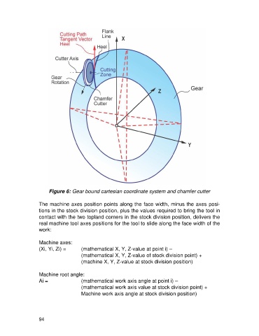
Figure 6: Gear bound cartesian coordinate system and chamfer cutter

                   The machine axes position points along the face width, minus the axes posi-
                   tions in the stock division position, plus the values required to bring the tool in
                   contact with the two topland corners in the stock division position, delivers the
                   real machine tool axes positions for the tool to slide along the face width of the
                   work:

                   Machine axes:
                   (Xi, Yi, Zi) =      (mathematical X, Y, Z-value at point i) –
                                       (mathematical X, Y, Z-value of stock division point) +
                                       (machine X, Y, Z-value at stock division position)

                   Machine root angle:
                   Ai =                (mathematical work axis angle at point i) –
                                       (mathematical work axis value at stock division point) +
                                       Machine work axis angle at stock division position)


                   94