
Page 104 - Gear Technology Solutions
P. 104
8 Topland Chamfering
8.1 Different Methods for Face Hobbing and Face Milling
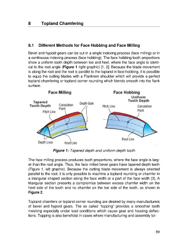
Bevel and hypoid gears can be cut in a single indexing process (face milling) or in
a continuous indexing process (face hobbing). The face hobbing tooth proportions
show a uniform tooth depth between toe and heel, where the face angle is identi-
cal to the root angle (Figure 1 right graphic) [1, 2]. Because the blade movement
is along the root and the root is parallel to the topland in face hobbing, it is possible
to equip the cutting blades with a Flankrem shoulder which will provide a perfect
topland chamfering or topland corner rounding which blends smooth into the flank
surface.
Figure 1: Tapered depth and uniform depth tooth
The face milling process produces tooth proportions, where the face angle is larg-
er than the root angle. Thus, the face milled bevel gears have tapered depth teeth
(Figure 1, left graphic). Because the cutting blade movement is always oriented
parallel to the root, it is only possible to machine a topland rounding or chamfer in
a triangular shaped section along the face width or a part of the face width [3]. A
triangular section presents a compromise between excess chamfer width on the
heel side of the tooth and no chamfer on the toe side of the tooth, as shown in
Figure 2.
Topland chamfers or topland corner rounding are desired by many manufacturers
of bevel and hypoid gears. The so called “topping” provides a smoother tooth
meshing especially under load conditions which cause gear and housing deflec-
tions. Topping is also beneficial in cases where manufacturing and assembly tol-
89