
Page 110 - Gear Technology Solutions
P. 110
8.4 Asymmetric Chamfers
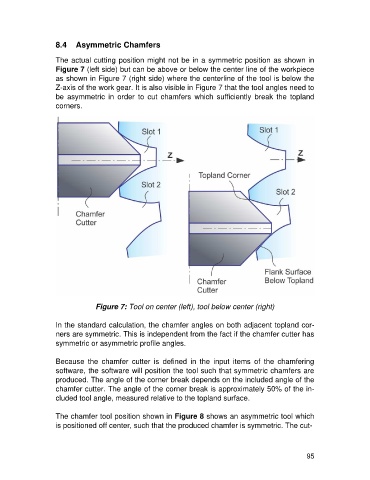
The actual cutting position might not be in a symmetric position as shown in
Figure 7 (left side) but can be above or below the center line of the workpiece
as shown in Figure 7 (right side) where the centerline of the tool is below the
Z-axis of the work gear. It is also visible in Figure 7 that the tool angles need to
be asymmetric in order to cut chamfers which sufficiently break the topland
corners.
Figure 7: Tool on center (left), tool below center (right)
In the standard calculation, the chamfer angles on both adjacent topland cor-
ners are symmetric. This is independent from the fact if the chamfer cutter has
symmetric or asymmetric profile angles.
Because the chamfer cutter is defined in the input items of the chamfering
software, the software will position the tool such that symmetric chamfers are
produced. The angle of the corner break depends on the included angle of the
chamfer cutter. The angle of the corner break is approximately 50% of the in-
cluded tool angle, measured relative to the topland surface.
The chamfer tool position shown in Figure 8 shows an asymmetric tool which
is positioned off center, such that the produced chamfer is symmetric. The cut-
95