
Page 106 - Gear Technology Solutions
P. 106
corners simultaneously and with alternating conventional cutting followed by climb
cutting, the chamfering time is greatly reduced, compared to existing chamfering
methods.
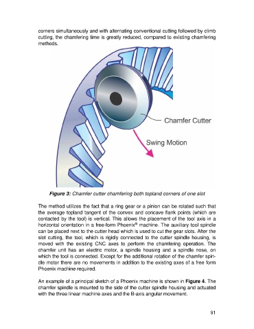
Figure 3: Chamfer cutter chamfering both topland corners of one slot
The method utilizes the fact that a ring gear or a pinion can be rotated such that
the average topland tangent of the convex and concave flank points (which are
contacted by the tool) is vertical. This allows the placement of the tool axis in a
®
horizontal orientation in a free-form Phoenix machine. The auxiliary tool spindle
can be placed next to the cutter head which is used to cut the gear slots. After the
slot cutting, the tool, which is rigidly connected to the cutter spindle housing, is
moved with the existing CNC axes to perform the chamfering operation. The
chamfer unit has an electric motor, a spindle housing and a spindle nose, on
which the tool is connected. Except for the additional rotation of the chamfer spin-
dle motor there are no movements in addition to the existing axes of a free form
Phoenix machine required.
An example of a principal sketch of a Phoenix machine is shown in Figure 4. The
chamfer spindle is mounted to the side of the cutter spindle housing and actuated
with the three linear machine axes and the B-axis angular movement.
91