
Page 111 - Gear Technology Solutions
P. 111
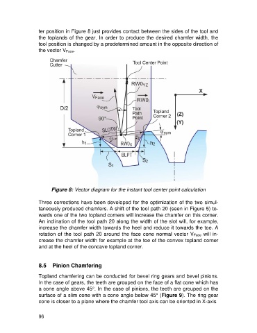
ter position in Figure 8 just provides contact between the sides of the tool and
                   the toplands of the gear. In order to produce the desired chamfer width, the
                   tool position is changed by a predetermined amount in the opposite direction of
                   the vector VFace.


                         Figure 8: Vector diagram for the instant tool center point calculation

                   Three corrections have been developed for the optimization of the two simul-
                   taneously produced chamfers. A shift of the tool path 20 (seen in Figure 5) to-
                   wards one of the two topland corners will increase the chamfer on this corner.
                   An inclination of the tool path 20 along the width of the slot will, for example,
                   increase the chamfer width towards the heel and reduce it towards the toe. A
                   rotation of the tool path 20 around the face cone normal vector VFace will in-
                   crease the chamfer width for example at the toe of the convex topland corner
                   and at the heel of the concave topland corner.


                   8.5  Pinion Chamfering

                   Topland chamfering can be conducted for bevel ring gears and bevel pinions.
                   In the case of gears, the teeth are grouped on the face of a flat cone which has
                   a cone angle above 45°. In the case of pinions, the teeth are grouped on the
                   surface of a slim cone with a cone angle below 45° (Figure 9). The ring gear
                   cone is closer to a plane where the chamfer tool axis can be oriented in X-axis


                   96