
Page 113 - Gear Technology Solutions
P. 113
Bi = (mathematical swing-axis position around X in Figure 9) +
(machine swing axis angle in stock division position) –
(mathematical swing-axis angle in stock division position)
8.6 Topland Chamfer Input Data
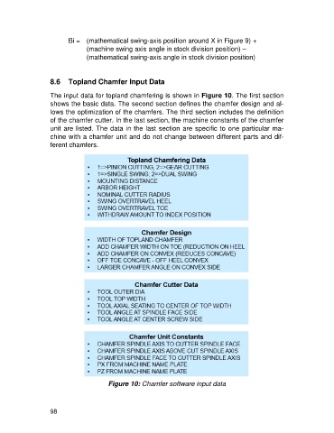
The input data for topland chamfering is shown in Figure 10. The first section
shows the basic data. The second section defines the chamfer design and al-
lows the optimization of the chamfers. The third section includes the definition
of the chamfer cutter. In the last section, the machine constants of the chamfer
unit are listed. The data in the last section are specific to one particular ma-
chine with a chamfer unit and do not change between different parts and dif-
ferent chamfers.
Figure 10: Chamfer software input data
98