
Page 105 - Gear Technology Solutions
P. 105
erances add up to large gearset position displacements. A further advantage of a
topland chamfer or rounding is the reduction of interference potential of gearsets.
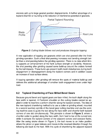
Figure 2: Cutting blade follows root and produces triangular topping
A new application of topping are gearsets which are shot peened after the finish
grinding operation. Such a final shot peening increases root bending strength bet-
ter than a shot peening before the grinding operation. There is no data which firm-
ly supports an enhancement of the flank surface strength or durability. However,
the shot peening after grinding caused some build-up around the craters formed
by the ball impacts. These build-ups present tooth mesh disturbances during tooth
engagement or disengagement along the topland corners and in addition cause
an increase of local surface stress.
A topping operation after grinding will remove the spots of material build-up and
delivers the additional advantage of smother tooth engagement even under high
load.
8.2 Topland Chamfering of Face Milled Bevel Gears
Because ground bevel and hypoid gears are face milled, the tooth depth along the
face width is tapered. A Flankrem shoulder on the cutting blades cannot be ap-
plied in order to machine a uniform chamfer along the topland corners. The idea of
the new topland chamfering method is to use a cutter or grinding wheel, mounted
to a second auxiliary spindle of the bevel gear cutting machine and use the exist-
ing machine axes to guide the tool along the face width and chamfer both topland
corners of one slot simultaneously. This principle is shown in Figure 3, where a
chamfer cutter is guided along the face width, from heel to toe of the curved slot,
while it contacts the topland corners of the adjacent convex and concave flanks.
After the swing stroke shown in Figure 3, the tool moves to an index position
where the pinion or gear indexes and moves in the reversed direction through the
following slot back to the heel. With this cycle of chamfering the adjacent topland
90