
Page 108 - Gear Technology Solutions
P. 108
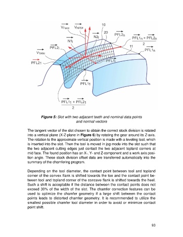
Figure 5: Slot with two adjacent teeth and nominal data points
                                                    and normal vectors

                   The tangent vector of the slot chosen to obtain the correct stock division is rotated
                   into a vertical plane (X-Z-plane in Figure 6) by rotating the gear around its Z-axis.
                   The rotation to the approximate vertical position is made with a leveling tool, which
                   is inserted into the slot. Then the tool is moved in jog mode into the slot such that
                   the two adjacent cutting edges just contact the two adjacent topland corners at
                   mid face. The found position has an X-, Y- and Z-component and a work axis posi-
                   tion angle. These stock division offset data are transferred automatically into the
                   summary of the chamfering program.

                   Depending  on  the tool diameter, the contact point  between  tool and  topland
                   corner of the convex flank is shifted towards the toe and the contact point be-
                   tween tool and topland corner of the concave flank is shifted towards the heel.
                   Such a shift is acceptable if the distance between the contact points does not
                   exceed 30% of the width of the slot. The chamfer correction features can be
                   used  to  optimize  the  chamfer  geometry  if  a  large  shift  between  the  contact
                   points leads to distorted chamfer geometry. It  is  recommended  to  utilize  the
                   smallest possible chamfer tool diameter in order to avoid or minimize contact
                   point shift.


                                                                                                      93