
Page 112 - Gear Technology Solutions
P. 112
direction (Figure 6) while the slot is being oriented horizontally for each instant
chamfer position by rotation of the ring gear around the Z-axis.
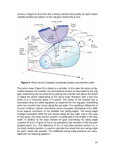
Figure 9: Pinion bound Cartesian coordinate system and chamfer cutter
The pinion cone (Figure 9) is closer to a cylinder. In this case the same config-
uration between the chamfer tool and topland corners as described for the ring
gear chamfering can be achieved by placing the chamfer tool above the pinion
or below the pinion (depending on the spiral angle direction) with a tool axis
which is in a horizontal plane (Y-Z plane). The center of the chamfer tool is
calculated using the same equations as explained for the ring gear chamfering
while the chamfer tool moves along the tool path. The significant difference of
the tool motions in pinion chamfering versus ring gear chamfering is the addi-
tional angular inclination of the chamfer tool (swing-angle). The swing angle
changes constantly while the tool travels along the tool path. Like in the case
of ring gears, the stock division position is conducted in the middle of the face
width. In addition to the stock division for gear chamfering the swing angle
(machine B-axis in Figure 4) has to be adjusted to the direction of the tool path
tangent vector VTan. The difference of VTan in any other position versus VTan in
the stock division position is used to calculate the actual tool axis swing-angle
for each instant tool position. The additional swing angle positions are calcu-
lated with the following equation:
97