
Page 280 - Gear Technology Solutions
P. 280
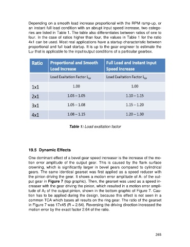
Depending on a smooth load increase proportional with the RPM ramp-up, or
                   an instant full load condition with an abrupt input speed increase, two catego-
                   ries are listed in Table 1. The table also differentiates between ratios of one to
                   four. In the case of ratios higher than four, the values in Table 1 for the ratio
                   4x1 can be used. Most real applications have a startup characteristic between
                   proportional and full load startup. It is up to the gear engineer to estimate the
                   LEF that is applicable to the input/output conditions of a particular gearbox.


                                              Table 1: Load exaltation factor


                   19.5  Dynamic Effects

                   One dominant effect of a bevel gear speed increaser is the increase of the mo-
                   tion  error  amplitude  of  the  output  gear.  This  is  caused  by  the  flank  surface
                   crowning,  which  is  significantly  larger  in  bevel  gears  compared  to  cylindrical
                   gears. The same identical gearset was first applied as a speed reducer with
                   the pinion driving the gear. It shows a motion error amplitude of A1 of the out-
                   put gear in Figure 7 (top graphic). Then, the gearset was used as a speed in-
                   creaser with the gear driving the pinion, which resulted in a motion error ampli-
                   tude of A2 of the output pinion, shown in the bottom graphic of Figure 7. Cau-
                   tion has to be applied during the design, because this effect is not seen in a
                   common TCA which bases all results on the ring gear. The ratio of the gearset
                   in Figure 7 was 17x45 (R = 2.64). Reversing the driving direction increased the
                   motion error by the exact factor 2.64 of the ratio.


                                                                                                     265