
Page 276 - Gear Technology Solutions
P. 276
surfaces. In the case of the opposite gear driving direction (clockwise), the
contact of pinion and gear flank is on the coast side which creates the opposite
force directions and attracts the gear towards the pinion. This will reduce or
eliminate the backlash which leads to an interruption of the lubrication film, fol-
lowed by scuffing on the flank surfaces in the area of high sliding velocities.
These are the areas with the largest distance to the pitch line [5].
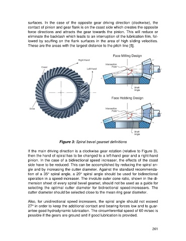
Figure 3: Spiral bevel gearset definitions
If the main driving direction is a clockwise gear rotation (relative to Figure 3),
then the hand of spiral has to be changed to a left-hand gear and a right-hand
pinion. In the case of a bidirectional speed increaser, the effects of the coast
side have to be reduced. This can be accomplished by reducing the spiral an-
gle and by increasing the cutter diameter. Against the standard recommenda-
tion of a 35° spiral angle, a 20° spiral angle should be used for bidirectional
operation in a speed-increaser. The involute outer cone ratio, shown in the di-
mension sheet of every spiral bevel gearset, should not be used as a guide for
selecting the optimal cutter diameter for bidirectional speed-increasers. The
cutter diameter should be selected close to the mean ring gear diameter.
Also, for unidirectional speed increasers, the spiral angle should not exceed
27° in order to keep the additional contact and bearing forces low and to guar-
antee good hydrodynamic lubrication. The circumferential speed of 60 m/sec is
possible if the gears are ground and if good lubrication is provided.
261