
Page 281 - Gear Technology Solutions
P. 281
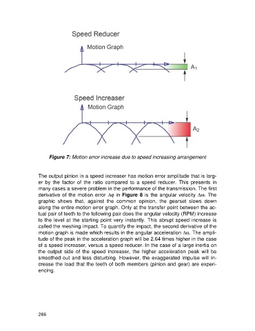
Figure 7: Motion error increase due to speed increasing arrangement


                   The output pinion in a speed increaser has motion error amplitude that is larg-
                   er  by  the  factor  of  the  ratio  compared  to  a  speed  reducer.  This  presents  in
                   many cases a severe problem in the performance of the transmission. The first

                   derivative of the motion error Djin Figure 8 is the angular velocity Dw. The
                   graphic  shows  that,  against  the  common  opinion,  the  gearset  slows  down
                   along the entire motion error graph. Only at the transfer point between the ac-
                   tual pair of teeth to the following pair does the angular velocity (RPM) increase
                   to the level at the starting point very instantly. This abrupt speed increase is
                   called the meshing impact. To quantify the impact, the second derivative of the
                   motion graph is made which results in the angular acceleration Da. The ampli-
                   tude of the peak in the acceleration graph will be 2.64 times higher in the case
                   of a speed increaser, versus a speed reducer. In the case of a large inertia on
                   the  output  side  of  the  speed  increaser,  the  higher  acceleration  peak  will  be
                   smoothed out and less disturbing. However, the exaggerated impulse will in-
                   crease the load that the teeth of both members (pinion and gear) are experi-
                   encing.


                   266