
Page 275 - Gear Technology Solutions
P. 275
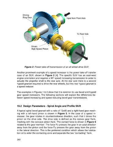
Figure 2: Power take-off transmission of an all-wheel drive SUV

                   Another prominent example of a speed increaser is the power take-off transfer
                   case of an SUV, shown in Figure 2 [4]. The specific SUV has an east-west
                   engine orientation and requires a 90° speed increasing transmission in order to
                   actuate the propellor shaft to the rear axle. At the rear axle there is a second
                   hypoid gearset required to drive the rear wheels, but this rear hypoid gearset is
                   a speed reducer.

                   The examples in Figures 1 & 2 show that it is common to use bevel and hypoid
                   gear speed increasers. The following sections will explain the differences be-
                   tween speed increasing and speed reducing bevel gear transmissions.


                   19.2  Design Parameters - Spiral Angle and Profile Shift

                   A typical spiral bevel gearset with a ratio of 13x45 and a right-hand gear mesh-
                   ing  with  a left-hand  pinion  is shown in  Figure  3.  In  the  case of  a speed in-
                   creaser, the gear rotates in counterclockwise direction, such that it drives the
                   pinion on the drive side. The drive side is defined as the convex gear flank,
                   meshing with the concave pinion flank. The contact force is shown in Figure 6
                   related to the gear member. The force Fz presses the gear in an axial direction
                   away from the pinion and the force Fy presses the gear away from the pinion
                   in the lateral direction. This is the preferred condition which allows the lubrica-
                   tion oil to enter the contacting zone and separate the two “contacting” flank


                   260