
Page 277 - Gear Technology Solutions
P. 277
Profile shift might be necessary for the ratio shown in Figure 3 in order to avoid
undercut and achieve a large active working profile. For speed increasers with
a ratio greater than 3, the root transition of both the driving gear and the driven
pinion are prone to scuffing. In order to keep the sliding velocities low, close to
the transition to the root area, the profile shift of pinion and gear should be ze-
ro or very low. This translates to an addendum modification factor which re-
sults in a pinion and gear dedendum (listed in the dimension sheet) which is
about 50% of the working depth.
19.3 Specific Sliding and Lubrication
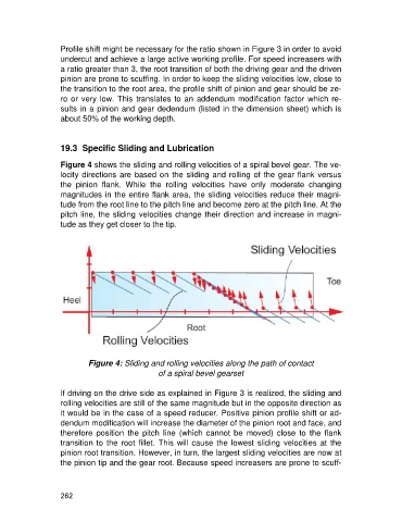
Figure 4 shows the sliding and rolling velocities of a spiral bevel gear. The ve-
locity directions are based on the sliding and rolling of the gear flank versus
the pinion flank. While the rolling velocities have only moderate changing
magnitudes in the entire flank area, the sliding velocities reduce their magni-
tude from the root line to the pitch line and become zero at the pitch line. At the
pitch line, the sliding velocities change their direction and increase in magni-
tude as they get closer to the tip.
Figure 4: Sliding and rolling velocities along the path of contact
of a spiral bevel gearset
If driving on the drive side as explained in Figure 3 is realized, the sliding and
rolling velocities are still of the same magnitude but in the opposite direction as
it would be in the case of a speed reducer. Positive pinion profile shift or ad-
dendum modification will increase the diameter of the pinion root and face, and
therefore position the pitch line (which cannot be moved) close to the flank
transition to the root fillet. This will cause the lowest sliding velocities at the
pinion root transition. However, in turn, the largest sliding velocities are now at
the pinion tip and the gear root. Because speed increasers are prone to scuff-
262