
Page 285 - Gear Technology Solutions
P. 285
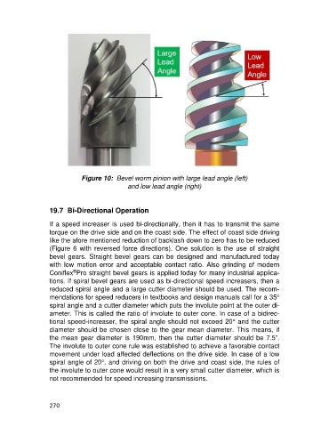
Figure 10:  Bevel worm pinion with large lead angle (left)
                                                and low lead angle (right)


                   19.7  Bi-Directional Operation

                   If a speed increaser is used bi-directionally, then it has to transmit the same
                   torque on the drive side and on the coast side. The effect of coast side driving
                   like the afore mentioned reduction of backlash down to zero has to be reduced
                   (Figure  6  with  reversed  force  directions).  One  solution  is  the  use  of  straight
                   bevel  gears.  Straight  bevel  gears  can  be  designed  and  manufactured  today
                   with  low  motion  error  and  acceptable  contact  ratio.  Also  grinding  of  modern
                            ®
                   Coniflex Pro straight bevel gears is applied today for many industrial applica-
                   tions. If spiral bevel gears are used as bi-directional speed increasers, then a
                   reduced spiral angle and a large cutter diameter should be used. The recom-
                   mendations for speed reducers in textbooks and design manuals call for a 35°
                   spiral angle and a cutter diameter which puts the involute point at the outer di-
                   ameter. This is called the ratio of involute to outer cone. In case of a bidirec-
                   tional speed-increaser, the spiral angle should not exceed 20° and the cutter
                   diameter should be chosen close to the gear mean diameter. This means, if
                   the mean gear diameter is 190mm, then the cutter diameter should be 7.5”.
                   The involute to outer cone rule was established to achieve a favorable contact
                   movement under load affected deflections on the drive side. In case of a low
                   spiral angle of 20°, and driving on both the drive and coast side, the rules of
                   the involute to outer cone would result in a very small cutter diameter, which is
                   not recommended for speed increasing transmissions.


                   270