
Page 283 - Gear Technology Solutions
P. 283
A lubrication film interruption cannot be compensated in the design calculation
of the gearset in the case of a higher output inertia. Because the flank separa-
tion is more likely with ratios greater than 2, it is required to design the Ease-
Off of a gearset with a ratio larger than 2 nearly conjugate and account for the
prevention of edge contact in case of deflections and component tolerances,
®
by applying blended Toprem and kinematic heel relief.
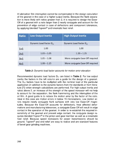
Table 2: Dynamic load factor accounts for motion error elevation
Recommended dynamic load factors DLF are listed in Table 2. For low output
inertia the factors in the left column are a guide for the design of a gearset.
The DLF factors have to be multiplied with the nominal load of the particular
application (in addition to the dynamic factors from the standards or from litera-
ture [7]) when strength calculations are performed. For high output inertia and
ratios above 2, an increase of the strength of the speed increaser will not help
to account for the separation, the flank hammering and the interruption of the
oil film. A good guide is to reduce the motion error by the factor of the ratio.
Ideal in this case are motion errors in below 15 microradians. Low motion er-
rors require nearly conjugate flank surfaces with very low Ease-Off magni-
tudes. Because the Ease-Off accounts for deflections, heat affected defor-
mations and manufacturing tolerances, a conjugate Ease-Off will result in edge
contact in the operation of the gearset. In order to re-establish the required in-
sensitivity of the gearset and prevent edge contact, the conjugate design re-
®
quires blended Toprem in the pinion and gear member as well as a kinematic
heel relief. Because speed increasers for power transmissions should be
®
ground, Toprem and end relief are easy to realize and are standard features
of bevel gear grinding machines.
268