
Page 279 - Gear Technology Solutions
P. 279
19.4 Starting at Full Output Load
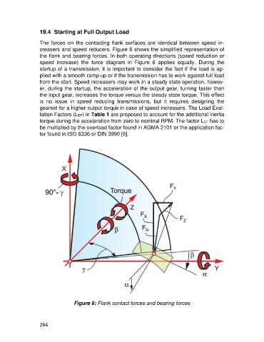
The forces on the contacting flank surfaces are identical between speed in-
creasers and speed reducers. Figure 6 shows the simplified representation of
the flank and bearing forces. In both operating directions (speed reduction or
speed increase) the force diagram in Figure 6 applies equally. During the
startup of a transmission, it is important to consider the fact if the load is ap-
plied with a smooth ramp-up or if the transmission has to work against full load
from the start. Speed increasers may work in a steady state operation, howev-
er, during the startup, the acceleration of the output gear, turning faster than
the input gear, increases the torque versus the steady state torque. This effect
is no issue in speed reducing transmissions, but it requires designing the
gearset for a higher output torque in case of speed increasers. The Load Exal-
tation Factors (LEF) in Table 1 are proposed to account for the additional inertia
torque during the acceleration from zero to nominal RPM. The factor LEF has to
be multiplied by the overload factor found in AGMA 2101 or the application fac-
tor found in ISO 6336 or DIN 3990 [6].
Figure 6: Flank contact forces and bearing forces
264