
Page 274 - Gear Technology Solutions
P. 274
19 Bevel Gear Speed Increasers
19.1 What is Different in Speed Increasers versus Speed Reducers?
For cylindrical gears, speed increasing transmission stages are well known
and regarding profile shift, preferred pressure angles and helix angles a set of
rules applies, which is not much different from the rules for speed reducers [1].
It is important to acknowledge that basically a speed increaser has to be de-
signed just like a speed reducer, but then the gear with the lower number of
teeth is the output. Of course, the torque and the speed of the gear with the
lower number of teeth (output) and the gear with the higher number of teeth
(input) must be the same as if this transmission was used as a speed reducer.
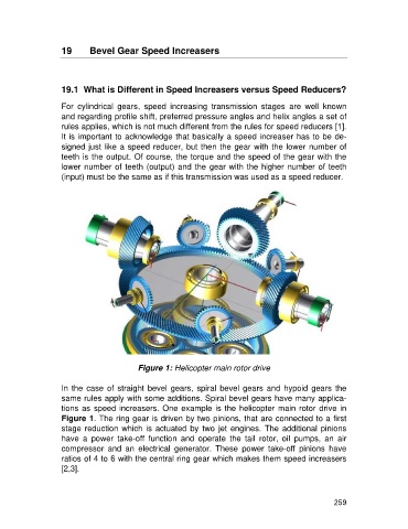
Figure 1: Helicopter main rotor drive
In the case of straight bevel gears, spiral bevel gears and hypoid gears the
same rules apply with some additions. Spiral bevel gears have many applica-
tions as speed increasers. One example is the helicopter main rotor drive in
Figure 1. The ring gear is driven by two pinions, that are connected to a first
stage reduction which is actuated by two jet engines. The additional pinions
have a power take-off function and operate the tail rotor, oil pumps, an air
compressor and an electrical generator. These power take-off pinions have
ratios of 4 to 6 with the central ring gear which makes them speed increasers
[2,3].
259