
Page 442 - Gear Technology Solutions
P. 442
Third plunge feed rate (see Tables 1, 2 & 3).
Power in excess of idle will limit the maximal power draw and abort the cycle
if the input value is exceeded.
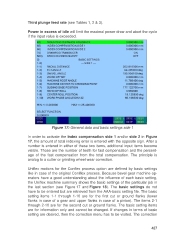
Figure 17: General data and basic settings side 1
In order to activate the index compensation side 1 and/or side 2 in Figure
17, the amount of total indexing error is entered with the opposite sign. After a
number is entered in either of these two items, additional input items become
visible. Those are the number of teeth for fast compensation and the percent-
age of the fast compensation from the total compensation. The principle is
analog to a cutter or grinding wheel wear correction.
Uniflex motions for the Conflex process option are defined by basic settings
like in case of the original Coniflex process. Because bevel gear machine op-
erators have a good understanding about the influence of each basic setting,
the Uniflex machine summary shows the basic settings of the particular job in
the last section (see Figure 17 and Figure 18). The basic settings do not
have to be entered but are retrieved from the AAA-basic setting file. The basic
setting items 1-1 through 1-10 are for the first cut or ground flanks (lower
flanks in case of a gear and upper flanks in case of a pinion). The items 2-1
through 2-10 are for the second cut or ground flanks. The basic setting items
are for information only and cannot be changed. If changes in terms of basic
setting are desired, then the correction menu has to be visited. The correction
427