
Page 445 - Gear Technology Solutions
P. 445
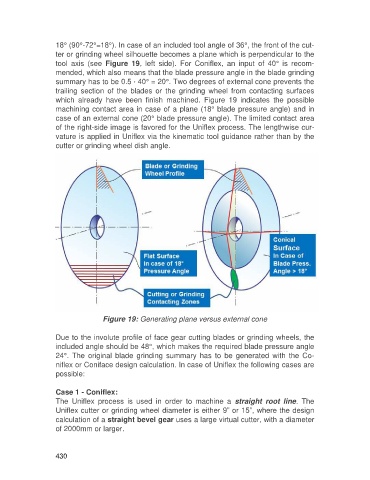
18° (90°-72°=18°). In case of an included tool angle of 36°, the front of the cut-
                   ter or grinding wheel silhouette becomes a plane which is perpendicular to the
                   tool  axis  (see  Figure  19,  left  side).  For  Coniflex,  an  input  of  40°  is  recom-
                   mended, which also means that the blade pressure angle in the blade grinding
                   summary has to be 0.5 * 40° = 20°. Two degrees of external cone prevents the
                   trailing  section  of  the  blades  or  the  grinding  wheel  from  contacting  surfaces
                   which  already  have  been  finish  machined.  Figure  19  indicates  the  possible
                   machining contact area in case of a plane (18° blade pressure angle) and in
                   case of an external cone (20° blade pressure angle). The limited contact area
                   of the right-side image is favored for the Uniflex process. The lengthwise cur-
                   vature is applied in Uniflex via the kinematic tool guidance rather than by the
                   cutter or grinding wheel dish angle.


                                   Figure 19: Generating plane versus external cone

                   Due to the involute profile of face gear cutting blades or grinding wheels, the
                   included angle should be 48°, which makes the required blade pressure angle
                   24°.  The  original  blade  grinding  summary  has  to  be  generated  with  the  Co-
                   niflex or Coniface design calculation. In case of Uniflex the following cases are
                   possible:

                   Case 1 - Coniflex:
                   The  Uniflex  process  is  used  in  order  to  machine  a  straight  root  line.  The
                   Uniflex cutter or grinding wheel diameter is either 9” or 15”, where the design
                   calculation of a straight bevel gear uses a large virtual cutter, with a diameter
                   of 2000mm or larger.


                   430