
Page 438 - Gear Technology Solutions
P. 438
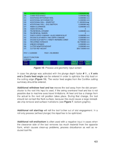
Figure 15: Process and geometry input screen

                   In case the plunge was activated with the plunge depth factor ≠ 0., a X axis
                   and a Z-axis feed angle can be entered in order to optimize the chip load on
                   the cutting edge (Figure 15). The vector feed angles from the Coniflex cutting
                   summary should be entered.

                   Additional withdraw heel and toe moves the tool away from the slot perpen-
                   dicular to the root this input is used, if the swing overtravel heel and toe is not
                   possible due to machine axes travel limitations. At heel and toe a change from
                   the  actual  to  the  next  roll  position  takes  place.  During  that  change,  the  tool
                   should not contact the flank surface, because this could cause a large immedi-
                   ate chip removal and surface mutilations (see Figure 7, bottom graphic).


                   Additional roll start/top will roll the tool further out of slot engagement. In a
                   roll only process (without plunge) this input has to be optimized.


                   Additional roll end/bottom is often used with a negative input in cases when
                   the clearance  side of the tool removes  too much material  from the  opposite
                   flank,  which  causes  clean-up  problems,  process  disturbance  as  well  as  re-
                   duced tool life.


                                                                                                     423