
Page 341 - Gear Technology Solutions
P. 341
24.2 Vector Feed Angle Convention
During the past years, several different types of vector feed have been devel-
oped and are in production worldwide. There are three criteria for the optimal
vector feed:
· Avoiding mutilations during plunge or withdraw
· Tool life
· Machine performance and power draw
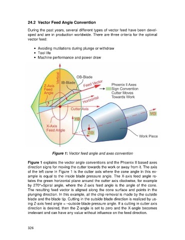
Figure 1: Vector feed angle and axes convention
Figure 1 explains the vector angle conventions and the Phoenix II based axes
direction signs for moving the cutter towards the work or away from it. The axis
of the left cone in Figure 1 is the cutter axis where the cone angle in this ex-
ample is equal to the inside blade pressure angle. The X-axis feed angle ro-
tates the green horizontal plane around the cutter axis clockwise, for example
by 270°+Spiral angle, where the Z-axis feed angle is the angle of the cone.
The resulting feed vector is aligned along the cone surface and points in the
plunging direction. In this example, all the chip removal is made by the outside
blade and the blade tip. Cutting in the outside blade direction is realized by us-
ing Z-axis feed angle = –outside blade pressure angle. If a cutting in cutter axis
direction is desired, then the Z-angle is set to zero and the X-angle becomes
irrelevant and can have any value without influence on the feed direction.
326