
Page 344 - Gear Technology Solutions
P. 344
The standard face hobbing pinion plunge vector feed as shown in Figure 3 in
combination with an optimized plunge roll position shows the optimal cutting re-
sults. A blade geometry optimization might be necessary if there are witness
marks of chip dragging on the convex flank surfaces, but no scratches on the side
reliefs of the pressure angle side on the inside blades. The recommendation is to
use a larger blade top width and increase the side relief angle of the inside blades
by up to 4° [2]
24.5 Extreme Vector Feed
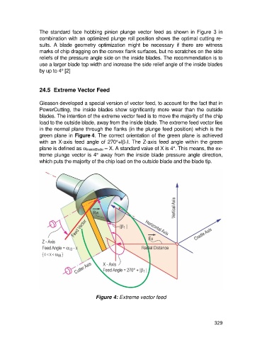
Gleason developed a special version of vector feed, to account for the fact that in
PowerCutting, the inside blades show significantly more wear than the outside
blades. The intention of the extreme vector feed is to move the majority of the chip
load to the outside blade, away from the inside blade. The extreme feed vector lies
in the normal plane through the flanks (in the plunge feed position) which is the
green plane in Figure 4. The correct orientation of the green plane is achieved
with an X-axis feed angle of 270°+Ib 1I. The Z-axis feed angle within the green
plane is defined as a InsideBlade – X. A standard value of X is 4°. This means, the ex-
treme plunge vector is 4° away from the inside blade pressure angle direction,
which puts the majority of the chip load on the outside blade and the blade tip.
Figure 4: Extreme vector feed
329