
Page 337 - Gear Technology Solutions
P. 337
Also, for face milling, the simplified top slope angle calculation explained in
Figure 5 is used. The blade height setting is achieved with the method
explained in Figure 3. The tip of the OB-blade cutting edge and the tip of the
IB-blade clearance side will touch the surface of the stop which will achieve the
correct stepping for the smoothest possible root bottom. In other words, the
blade height positions of OB- and IB-blade can be both adjusted with the OB-
blade height setting.
®
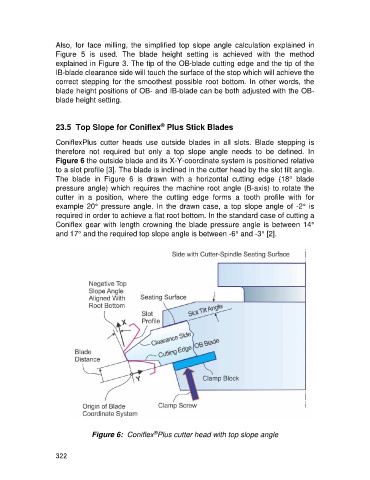
23.5 Top Slope for Coniflex Plus Stick Blades
ConiflexPlus cutter heads use outside blades in all slots. Blade stepping is
therefore not required but only a top slope angle needs to be defined. In
Figure 6 the outside blade and its X-Y-coordinate system is positioned relative
to a slot profile [3]. The blade is inclined in the cutter head by the slot tilt angle.
The blade in Figure 6 is drawn with a horizontal cutting edge (18° blade
pressure angle) which requires the machine root angle (B-axis) to rotate the
cutter in a position, where the cutting edge forms a tooth profile with for
example 20° pressure angle. In the drawn case, a top slope angle of -2° is
required in order to achieve a flat root bottom. In the standard case of cutting a
Coniflex gear with length crowning the blade pressure angle is between 14°
and 17° and the required top slope angle is between -6° and -3° [2].
®
Figure 6: Coniflex Plus cutter head with top slope angle
322