
Page 346 - Gear Technology Solutions
P. 346
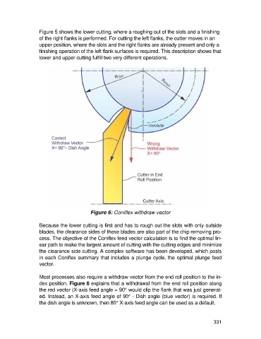
Figure 5 shows the lower cutting, where a roughing out of the slots and a finishing
                   of the right flanks is performed. For cutting the left flanks, the cutter moves in an
                   upper position, where the slots and the right flanks are already present and only a
                   finishing operation of the left flank surfaces is required. This description shows that
                   lower and upper cutting fulfill two very different operations.


                                           Figure 6: Coniflex withdraw vector

                   Because the lower cutting is first and has to rough out the slots with only outside
                   blades, the clearance sides of these blades are also part of the chip removing pro-
                   cess. The objective of the Coniflex feed vector calculation is to find the optimal lin-
                   ear path to make the largest amount of cutting with the cutting edges and minimize
                   the clearance side cutting. A complex software has been developed, which posts
                   in each Coniflex summary that includes a plunge cycle, the optimal plunge feed
                   vector.

                   Most processes also require a withdraw vector from the end roll position to the in-
                   dex position. Figure 6 explains that a withdrawal from the end roll position along
                   the red vector (X-axis feed angle = 90° would clip the flank that was just generat-
                   ed. Instead, an X-axis feed angle of 90° - Dish angle (blue vector) is required. If
                   the dish angle is unknown, then 80° X-axis feed angle can be used as a default.


                                                                                                     331