
Page 343 - Gear Technology Solutions
P. 343
clean up during the following generating roll of a pinion or at the full depth position
of a Formate plunge. The result is considered a mutilation [1].
24.4 Standard Pinion Face Hobbing Vector Feed
The idea behind this vector feed version is to define the feed vector in a horizontal
plane, perpendicular to the pinion axis. This geometry requires only the two hori-
zontal axes of the Phoenix machines (X- and Z-axis) to move during the plunge.
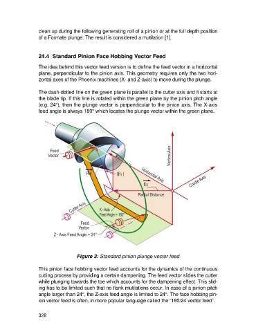
The dash-dotted line on the green plane is parallel to the cutter axis and it starts at
the blade tip. If this line is rotated within the green plane by the pinion pitch angle
(e.g. 24°), then the plunge vector is perpendicular to the pinion axis. The X-axis
feed angle is always 180° which locates the plunge vector within the green plane.
Figure 3: Standard pinion plunge vector feed
This pinion face hobbing vector feed accounts for the dynamics of the continuous
cutting process by providing a certain dampening. The feed vector slides the cutter
while plunging towards the toe which accounts for the dampening effect. This slid-
ing has to be limited such that no flank mutilations occur. In case of a pinion pitch
angle larger than 24°, the Z-axis feed angle is limited to 24°. The face hobbing pin-
ion vector feed is often, in more popular language called the “180/24 vector feed”.
328