
Page 270 - Gear Technology Solutions
P. 270
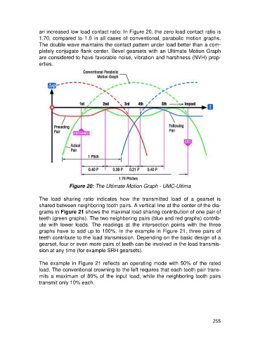
an increased low load contact ratio. In Figure 20, the zero load contact ratio is
                   1.70, compared to 1.0 in all cases of conventional, parabolic motion graphs.
                   The double wave maintains the contact pattern under load better than a com-
                   pletely conjugate flank center. Bevel gearsets with an Ultimate Motion Graph
                   are considered to have favorable noise, vibration and harshness (NVH) prop-
                   erties.


                                  Figure 20: The Ultimate Motion Graph - UMC-Ultima

                   The  load  sharing  ratio  indicates  how  the  transmitted  load  of  a  gearset  is
                   shared between neighboring tooth pairs. A vertical line at the center of the dia-
                   grams in Figure 21 shows the maximal load sharing contribution of one pair of
                   teeth (green graphs). The two neighboring pairs (blue and red graphs) contrib-
                   ute  with  lower  loads.  The  readings  at  the  intersection  points  with  the  three
                   graphs have to add up to 100%. In the example in Figure 21, three pairs of
                   teeth contribute to the load transmission. Depending on the basic design of a
                   gearset, four or even more pairs of teeth can be involved in the load transmis-
                   sion at any time (for example SRH gearsets).

                   The example in Figure 21 reflects an operating mode with 50% of the rated
                   load. The conventional crowning to the left requires that each tooth pair trans-
                   mits a  maximum of  80% of the input load,  while  the  neighboring tooth  pairs
                   transmit only 10% each.


                                                                                                     255