
Page 269 - Gear Technology Solutions
P. 269
The eighth and final step of this development was devoted to re-establishing a
sufficient blended Toprem relief along the root of the gear. This was required
because the initial relief (step 1) diminished during the previous development
steps. A Toprem depth of 3.5mm and a Toprem radius of 35mm was imple-
mented only on the coast side gear grinding profile. Figure 18 reflects a highly
optimized selective crowning development. Both coast and drive side have a
transmission error in the range of only 5mrad. Yet, the selective protection
against edge contact in operation is significant.
Conventional Design Selective Crowning Design
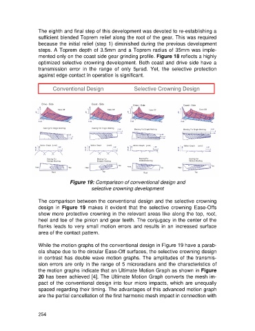
Figure 19: Comparison of conventional design and
selective crowning development
The comparison between the conventional design and the selective crowning
design in Figure 19 makes it evident that the selective crowning Ease-Offs
show more protective crowning in the relevant areas like along the top, root,
heel and toe of the pinion and gear teeth. The conjugacy in the center of the
flanks leads to very small motion errors and results in an increased surface
area of the contact pattern.
While the motion graphs of the conventional design in Figure 19 have a parab-
ola shape due to the circular Ease-Off surfaces, the selective crowning design
in contrast has double wave motion graphs. The amplitudes of the transmis-
sion errors are only in the range of 5 microradians and the characteristics of
the motion graphs indicate that an Ultimate Motion Graph as shown in Figure
20 has been achieved [4]. The Ultimate Motion Graph converts the mesh im-
pact of the conventional design into four micro impacts, which are unequally
spaced regarding their timing. The advantages of this advanced motion graph
are the partial cancellation of the first harmonic mesh impact in connection with
254