
Page 258 - Gear Technology Solutions
P. 258
Section 8 is an end-relief correction either at the heel or at the toe. It can only
be applied to a non-generated member. A complex motion at the end of grind-
ing each Formate gear slot (Formrolling) forms the relief end-relief section. Al-
so, this correction reliefs both flanks of one slot simultaneously while grinding
wheel moves from the position it grinds both flanks away from the flank grind-
ing contact without causing any secondary grinding contact with the finished
flank surfaces.
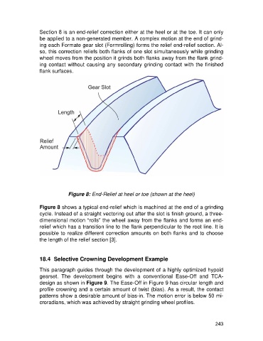
Figure 8: End-Relief at heel or toe (shown at the heel)
Figure 8 shows a typical end-relief which is machined at the end of a grinding
cycle. Instead of a straight vectoring out after the slot is finish ground, a three-
dimensional motion “rolls” the wheel away from the flanks and forms an end-
relief which has a transition line to the flank perpendicular to the root line. It is
possible to realize different correction amounts on both flanks and to choose
the length of the relief section [3].
18.4 Selective Crowning Development Example
This paragraph guides through the development of a highly optimized hypoid
gearset. The development begins with a conventional Ease-Off and TCA-
design as shown in Figure 9. The Ease-Off in Figure 9 has circular length and
profile crowning and a certain amount of twist (bias). As a result, the contact
patterns show a desirable amount of bias-in. The motion error is below 50 mi-
croradians, which was achieved by straight grinding wheel profiles.
243