
Page 255 - Gear Technology Solutions
P. 255
heel to the center, where it has a plateau. From there it rises to the exit point.
In all cases, there are very small, neglectable side effects in the single micron
range. This UMC demonstration proves that higher order corrections can be
achieved on one flank, without noticeable side effects on the opposite flank,
although both flanks are manufactured with the same cutter or grinding wheel
simultaneously.
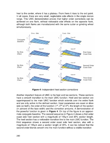
Figure 4: Independent heel section corrections
Another important feature of UMC is the heel and toe sections. These sections
have a smooth transition to the main UMC function. Heel and toe section are
superimposed to the main UMC function which extends over the entire flank
and are only active in the defined section. Input parameters are coast or drive
st
nd
rd
side (or both), the order of the function (1 , 2 or 3 ), the length of the section
(in percent of the face width) and the correction amounts. A demonstration of
the powerful function is given in Figure 4. On top of the figure is an approxi-
mate conjugate baseline. The second sequence in Figure 4 shows a first order
coast side heel section with a magnitude of 100mm and 30% section length.
The heel section has a noticeable transition line to the main UMC function. The
third sequence shows a second order coast side heel section, also with a
magnitude of 100mm and a section length of 30%. It can be noticed that the
second order blends smooth into the main function without a visible transition
240