
Page 256 - Gear Technology Solutions
P. 256
line. A third order function with the same input parameters as before was used
in the fourth sequence of Figure 4. Here the transition is entirely masked by
the equal second derivative of the third order function to the main surface func-
tion. No side effects can be noticed in all three correction cases in Figure 4.
18.3 The Eight Sections of Selective Crowning
Selective crowning combines the UMC corrections with Toprem and Flankrem
as well as with the special end-relief correction. There are eight different flank
sections defined, each of which can be addressed for optimizations inde-
pendently from all other sections.
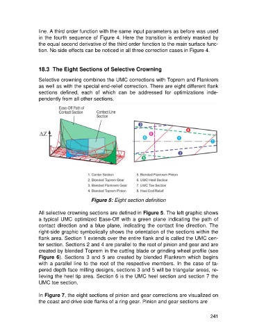
Figure 5: Eight section definition
All selective crowning sections are defined in Figure 5. The left graphic shows
a typical UMC optimized Ease-Off with a green plane indicating the path of
contact direction and a blue plane, indicating the contact line direction. The
right-side graphic symbolically shows the orientation of the sections within the
flank area. Section 1 extends over the entire flank and is called the UMC cen-
ter section. Sections 2 and 4 are parallel to the root of pinion and gear and are
created by blended Toprem in the cutting blade or grinding wheel profile (see
Figure 6). Sections 3 and 5 are created by blended Flankrem which begins
with a parallel line to the root of the respective members. In the case of ta-
pered depth face milling designs, sections 3 and 5 will be triangular areas, re-
lieving the heel tip area. Section 6 is the UMC heel section and section 7 the
UMC toe section.
In Figure 7, the eight sections of pinion and gear corrections are visualized on
the coast and drive side flanks of a ring gear. Pinion and gear sections are
241