
Page 254 - Gear Technology Solutions
P. 254
In Figure 2 the typical polynomials used for the higher order basic setting
changes are documented. These interactive setting changes are utilized with
rather sophisticated mathematics to achieve almost any flank form modifica-
tions without noticeable side effects. However, these roll-position driven cor-
rections are only possible on the generated members.
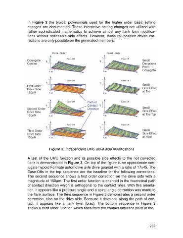
Figure 3: Independent UMC drive side modifications
A test of the UMC function and its possible side effects to the not corrected
flank is demonstrated in Figure 3. On top of the figure is an approximate con-
jugate hypoid Formate automotive axle drive gearset with a ratio of 17x45. The
Ease-Offs in the top sequence are the baseline for the following corrections.
The second sequence shows a first order correction on the drive side with a
magnitude of 150mm. The first order function is oriented in the theoretical path
of contact direction which is orthogonal to the contact lines. With this orienta-
tion, it appears like a pressure angle and a spiral angle correction was made to
the flank surface. The third sequence in Figure 3 demonstrates a second order
correction, also on the drive side. Because it develops along the path of con-
tact, it appears like a flank twist (bias). The bottom sequence in Figure 3
shows a third order function which rises from the contact entrance point at the
239