
Page 250 - Gear Technology Solutions
P. 250
17.5 MicroPulse
If in addition to MicroForm and MicroShift a surface structure change with Micro-
Pulse should be applied, then a good starting point is the input parameters from
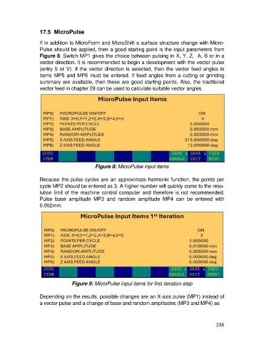
Figure 8. Switch MP1 gives the choice between pulsing in X, Y, Z, A, B or in a
vector direction. It is recommended to begin a development with the vector pulse
(entry 5 or V). If the vector direction is selected, then the vector feed angles in
items MP5 and MP6 must be entered. If feed angles from a cutting or grinding
summary are available, then these are good starting points. Also, the traditional
vector feed in chapter 29 can be used to calculate suitable vector angles.
Figure 8: MicroPulse input items
Because the pulse cycles are an approximate harmonic function, the points per
cycle MP2 should be entered as 3. A higher number will quickly come to the reso-
lution limit of the machine control computer and therefore is not recommended.
Pulse base amplitude MP3 and random amplitude MP4 can be entered with
0.002mm.
Figure 9: MicroPulse input items for first iteration step
Depending on the results, possible changes are an X-axis pulse (MP1) instead of
a vector pulse and a change of base and random amplitudes (MP3 and MP4) as
235