
Page 249 - Gear Technology Solutions
P. 249
17.4 MicroShift
After a finished MicroForm development, MicroShift can be activated in addition to
MicroForm by applying the input items shown in Figure 7. MicroPulse and Micro-
Shift are connected with the switch MP0. MP0 is used to make the input parame-
ters of MicroPulse and MicroShift visible. Developments for noise reduction should
begin with MicroPulse inactive. To accomplish this, the items MP2 to MP6 must be
entered with 0.000000. as shown in Figure 7.
There are only two input items for MicroShift. MicroShift provides a shift of the
ground surface structure relative to the tooth surface. MP7 defines the shift func-
tion. It can be selected either for a normal distribution, a sine-function or it can be
turned off. Both distribution methods are equally well suited, where the sine func-
tion with two highs and two lows appears more aggressive. A shift amplitude of 1.5
in connection with a sine-function would shift the surface structure on an 11-tooth
pinion to the maximum of 1.5 flat width at tooth number 3 and then back to zero at
tooth number 6. From there the shift is directed in negative direction to the mini-
mum at tooth number 9 and then back to one increment below zero at tooth num-
ber 11.
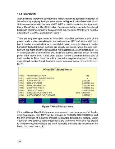
Figure 7: MicroShift input items
If the addition of MicroShift shows no improvement, or no improvement at the de-
sired frequencies, then MP7 can be changed to NORMAL DISTRIBUTION and
the shift amplitude MP8 can be changed for example between 0.3 and 2.5. Lower
values for MP8 address higher frequencies and vice versa. MicroShift has proven
to influence frequencies above the fourth harmonic and have little influence on the
first to third mesh harmonic.
234