
Page 234 - Gear Technology Solutions
P. 234
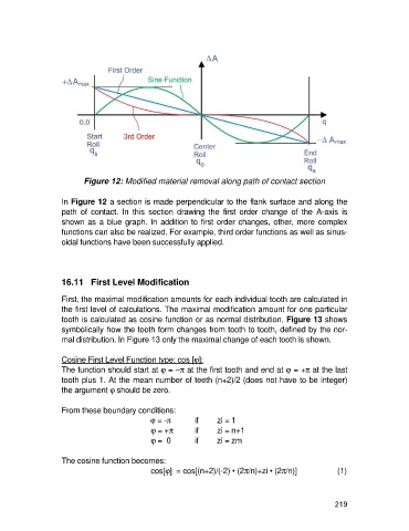
Figure 12: Modified material removal along path of contact section

                   In Figure 12 a section is made perpendicular to the flank surface and along the
                   path  of  contact.  In  this  section  drawing  the  first  order  change  of  the  A-axis  is
                   shown as a blue graph. In addition to first order changes, other, more complex
                   functions can also be realized. For example, third order functions as well as sinus-
                   oidal functions have been successfully applied.


                   16.11   First Level Modification

                   First, the maximal modification amounts for each individual tooth are calculated in
                   the first level of calculations. The maximal modification amount for one particular
                   tooth is calculated as cosine function or as normal distribution. Figure 13 shows
                   symbolically how the tooth form changes from tooth to tooth, defined by the nor-
                   mal distribution. In Figure 13 only the maximal change of each tooth is shown.

                   Cosine First Level Function type: cos [j]:
                   The function should start at j = –p at the first tooth and end at j = +p at the last
                   tooth plus 1. At the mean number of teeth (n+2)/2 (does not have to be integer)
                   the argument j should be zero.

                   From these boundary conditions:
                                              j = -p       if     zi = 1
                                              j = +p       if     zi = n+1
                                              j =  0       if     zi = zm

                   The cosine function becomes:
                                              cos[j]  = cos[(n+2)/(-2) • (2p/n)+zi • (2p/n)]                   (1)


                                                                                                     219