
Page 233 - Gear Technology Solutions
P. 233
scheme for such a machine is shown in Figure 8. The modifications are calculated
such that the average flank form of all the teeth of a gear with flank form scattering
will be identical to a gear without any modifications. Due to the roll position de-
pendency of the single tooth corrections, the tooth indexing and tooth thickness
will not vary from tooth to tooth, as long as the reference roll position is identical or
close to the tooth center point. The following machine motion modifications are
performed:
A-axis angle modifications
Y-axis position modifications (dependent on A-axis)
X-axis position modifications (dependent on A-axis)
Z-axis position modifications (dependent on A-axis)
The modification axes A, Y, X and Z are labeled in the machine structure shown in
Figure 8.
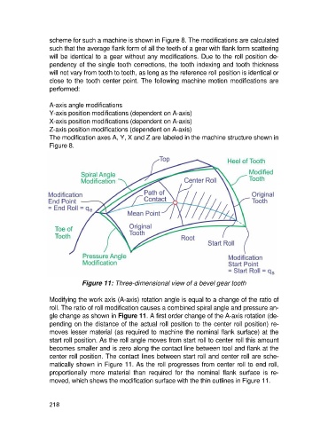
Figure 11: Three-dimensional view of a bevel gear tooth
Modifying the work axis (A-axis) rotation angle is equal to a change of the ratio of
roll. The ratio of roll modification causes a combined spiral angle and pressure an-
gle change as shown in Figure 11. A first order change of the A-axis rotation (de-
pending on the distance of the actual roll position to the center roll position) re-
moves lesser material (as required to machine the nominal flank surface) at the
start roll position. As the roll angle moves from start roll to center roll this amount
becomes smaller and is zero along the contact line between tool and flank at the
center roll position. The contact lines between start roll and center roll are sche-
matically shown in Figure 11. As the roll progresses from center roll to end roll,
proportionally more material than required for the nominal flank surface is re-
moved, which shows the modification surface with the thin outlines in Figure 11.
218