
Page 239 - Gear Technology Solutions
P. 239
A visualization of the control parameters for the wavelength and the amplitude is
given in Figure 14. Between toe and midface, the frequency factor fToe is 0.8
(longer wavelength). Between midface and heel, the frequency factor fHeel is 1.2
(shorter wavelength). At this point the mean roll position is introduced. The center
roll position is in case of hypoid pinions not at the geometrical center of the flanks.
The mean roll position can ensure a more centric second level modification func-
tion.
Equation (10) can be applied to the sole A-axis modification (equation (8)), or to a
modification of a combination of multiple axes.
16.14 Addition of a Dwell Section
Production manufacturing of gearsets with the MicroForm flank form scattering
technology revealed that in many practical applications the zero point of the sec-
ond level sine function at the center of roll position does not match the grid center
point of the CMM inspection. This effect leads to an increase of indexing errors in
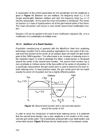
the inspection report. In order to eliminate this effect, a dwell section is introduced
around the center of the second level function. The second level function has a
zero amplitude at midface (center of the face width) at the center of roll position. In
a coordinate measurement, the grid center point is used to determine the tooth to-
tooth indexing error. In most practical cases, the grid center point will not match
exactly the center of roll position but has a slightly different position.
Figure 15: Second level function with a toe and heel section
around the center of roll
In order to avoid the introduction of tooth-to-tooth indexing errors, it is preferred
that the second level function has a zero amplitude at the location of the meas-
urement grid center point. This is preferably achieved with a toe dwell section and
a heel dwell section. Figure 15 shows the toe dwell section DToe between center
224