
Page 232 - Gear Technology Solutions
P. 232
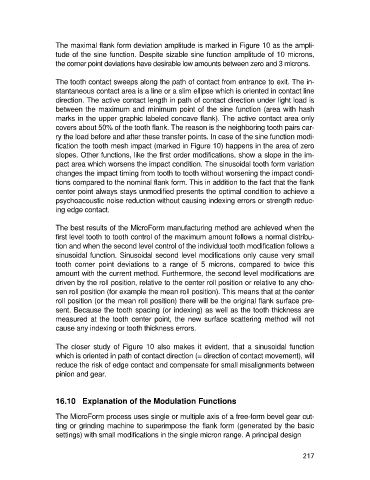
The maximal flank form deviation amplitude is marked in Figure 10 as the ampli-
                   tude of the sine function. Despite sizable sine function amplitude of 10 microns,
                   the corner point deviations have desirable low amounts between zero and 3 microns.

                   The tooth contact sweeps along the path of contact from entrance to exit. The in-
                   stantaneous contact area is a line or a slim ellipse which is oriented in contact line
                   direction. The active contact length in path of contact direction under light load is
                   between the maximum and minimum point of the sine function (area with hash
                   marks in the upper graphic labeled concave flank). The active contact area only
                   covers about 50% of the tooth flank. The reason is the neighboring tooth pairs car-
                   ry the load before and after these transfer points. In case of the sine function modi-
                   fication the tooth mesh impact (marked in Figure 10) happens in the area of zero
                   slopes. Other functions, like the first order modifications, show a slope in the im-
                   pact area which worsens the impact condition. The sinusoidal tooth form variation
                   changes the impact timing from tooth to tooth without worsening the impact condi-
                   tions compared to the nominal flank form. This in addition to the fact that the flank
                   center point always stays unmodified presents the optimal condition to achieve a
                   psychoacoustic noise reduction without causing indexing errors or strength reduc-
                   ing edge contact.

                   The best results of the MicroForm manufacturing method are achieved when the
                   first level tooth to tooth control of the maximum amount follows a normal distribu-
                   tion and when the second level control of the individual tooth modification follows a
                   sinusoidal function. Sinusoidal second level modifications only cause very small
                   tooth  corner  point  deviations  to  a  range  of  5  microns,  compared  to  twice  this
                   amount with the current method. Furthermore, the second level modifications are
                   driven by the roll position, relative to the center roll position or relative to any cho-
                   sen roll position (for example the mean roll position). This means that at the center
                   roll position (or the mean roll position) there will be the original flank surface pre-
                   sent. Because the tooth spacing (or indexing) as well as the tooth thickness are
                   measured at the tooth center point, the  new surface scattering method will  not
                   cause any indexing or tooth thickness errors.

                   The  closer  study  of  Figure  10  also  makes  it  evident,  that  a  sinusoidal  function
                   which is oriented in path of contact direction (= direction of contact movement), will
                   reduce the risk of edge contact and compensate for small misalignments between
                   pinion and gear.


                   16.10   Explanation of the Modulation Functions

                   The MicroForm process uses single or multiple axis of a free-form bevel gear cut-
                   ting or grinding machine to superimpose the flank form (generated by the basic
                   settings) with small modifications in the single micron range. A principal design


                                                                                                     217