
Page 231 - Gear Technology Solutions
P. 231
The modulation is applied in two levels. The first and higher-level controls the
maximal flank form deviation amplitude for each individual tooth. The first level
modification control has been defined by a cosine function or by a normal distribu-
tion. Also, other mathematical functions or random distributions could be applied
to the first level modification.
The second and lower level controls the modification on the individual tooth sur-
face itself. The second level has been defined as a first order, a third order or a
sinusoidal function. The second level modifications on each single tooth are not
conducted by common spiral angle and pressure angle corrections, but with roll
position dependent functions, which are developed based on the center point of
the flanks. Center point developed modifications will not show tooth thickness or
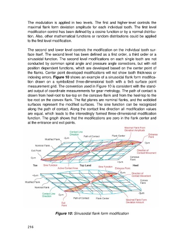
indexing errors. Figure 10 shows an example of a sinusoidal flank form modifica-
tion drawn on a symbolized three-dimensional tooth with a 9x5 surface point
measurement grid. The convention used in Figure 10 is consistent with the stand-
ard output of coordinate measurements for gear metrology. The path of contact is
drawn from heel-root to toe-top on the concave flank and from the heel-top to the
toe root on the convex flank. The flat planes are nominal flanks, and the wobbled
surfaces represent the modified surfaces. The sine function can be recognized
along the path of contact. Along the contact line direction all modification values
are equal, which leads to the interestingly formed three-dimensional modification
function. The graph shows that the modifications are zero in the flank center and
at the entrance and exit points.
Figure 10: Sinusoidal flank form modification
216