
Page 101 - Gear Technology Solutions
P. 101
7.6 Surface Optimization during Break-In of a Hunting Tooth Ratio
In order to achieve the break-in results described in the last paragraph it is im-
perative to design gearsets with hunting tooth ratios. Hunting tooth condition
can be established if the number of pinion or gear teeth of an integer ratio or a
common denominator ratio is increased by just one tooth. Now, during the
break-in every pinion tooth will mesh with every gear tooth. The influence of
this kinematic difference allows the teeth to become more equal as opposed to
developing their individual shapes in groups of 10 (in the above-mentioned ex-
ample).
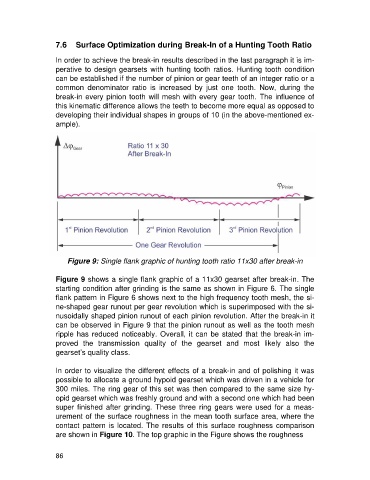
Figure 9: Single flank graphic of hunting tooth ratio 11x30 after break-in
Figure 9 shows a single flank graphic of a 11x30 gearset after break-in. The
starting condition after grinding is the same as shown in Figure 6. The single
flank pattern in Figure 6 shows next to the high frequency tooth mesh, the si-
ne-shaped gear runout per gear revolution which is superimposed with the si-
nusoidally shaped pinion runout of each pinion revolution. After the break-in it
can be observed in Figure 9 that the pinion runout as well as the tooth mesh
ripple has reduced noticeably. Overall, it can be stated that the break-in im-
proved the transmission quality of the gearset and most likely also the
gearset’s quality class.
In order to visualize the different effects of a break-in and of polishing it was
possible to allocate a ground hypoid gearset which was driven in a vehicle for
300 miles. The ring gear of this set was then compared to the same size hy-
opid gearset which was freshly ground and with a second one which had been
super finished after grinding. These three ring gears were used for a meas-
urement of the surface roughness in the mean tooth surface area, where the
contact pattern is located. The results of this surface roughness comparison
are shown in Figure 10. The top graphic in the Figure shows the roughness
86