
Page 55 - Gear Technology Solutions
P. 55
is directed such that the plane of action appears as a line that is tangential to
the two cone enveloping surfaces. The left side graphic in Figure 5 shows the
plane of action three-dimensionally and how it connects the two base ele-
ments.
The plane of action cannot be extended beyond its tangential contacting line
with the base element as shown in Figure 5. The plane of action only exists
where tooth engagement is possible, and it is different than the generating
gear plane (more specifically explained below).
There is, however, one difference from the true involute of cylindrical gears.
The rotation of pinion and gear does not occur in the normal plane but in the
transverse plane. Because of this difference, the flank profile of straight bevel
gears (and all other bevel gear types) is called Octoide. The Octoide is the an-
alog function of an involute and it provides to bevel gears the same ad-
vantages as an involute provides to cylindrical gears. Those advantages are
constant ratio, center distance insensitivity and ease of manufacturing.
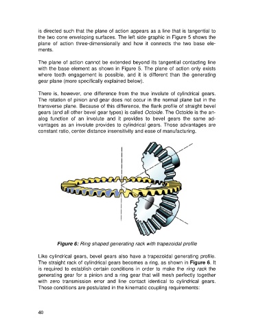
Figure 6: Ring shaped generating rack with trapezoidal profile
Like cylindrical gears, bevel gears also have a trapezoidal generating profile.
The straight rack of cylindrical gears becomes a ring, as shown in Figure 6. It
is required to establish certain conditions in order to make the ring rack the
generating gear for a pinion and a ring gear that will mesh perfectly together
with zero transmission error and line contact identical to cylindrical gears.
Those conditions are postulated in the kinematic coupling requirements:
40