
Page 59 - Gear Technology Solutions
P. 59
matches the presentation plane (base plane) precisely, that is the proof that a
conjugate and precisely rolling gearset was the input of this contact analysis
calculation.
The above experiment creating a conjugate straight bevel gearset is strictly
academic. Conjugacy is the basis of all gearsets manufactured in high volume
on dedicated manufacturing machines. A conjugate bevel gearset cannot be
used for a power transmission because manufacturing tolerances and load af-
fected deflections as well as material expansions and deformations under high
operating temperatures will result in edge contact and high load concentra-
tions. The load concentrations already start with moderate load and cause ma-
terial damage and considerable noise emission. Although conjugacy is used as
a reference for each design, predetermined amounts of length and profile
crowning are applied. The right amount of crowning makes a gearset quiet and
gives it the required load carrying capacity. The crowning is shown in the
Ease-Off graphics with the conjugate reference always being present as the
Ease-Off base plane. Several Ease-Off examples of a gearset with length and
profile crowning are shown in the proceedings of this chapter.
4.5 Perfect Conjugacy in Hypoid Gearsets
It begins to become more problematic for hypoid gears. Frequently the pitch
elements of crossed axes hypoid gears are drawn as cones. Even though the
face cones of hypoid gears and pinions are machined conical, the pitch ele-
ments are hyperboloids.
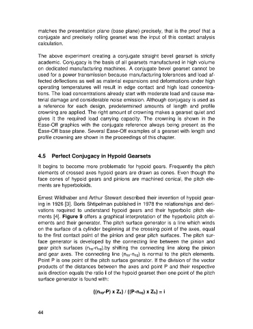
Ernest Wildhaber and Arthur Stewart described their invention of hypoid gear-
ing in 1926 [3]. Boris Shtipelman published in 1978 the relationships and deri-
vations required to understand hypoid gears and their hyperbolic pitch ele-
ments [4]. Figure 9 offers a graphical interpretation of the hyperbolic pitch el-
ements and their generator. The pitch surface generator is a line which winds
on the surface of a cylinder beginning at the crossing point of the axes, equal
to the first contact point of the pinion and gear pitch surfaces. The pitch sur-
face generator is developed by the connecting line between the pinion and
gear pitch surfaces (nop-nog).by shifting the connecting line along the pinion
and gear axes. The connecting line (nop-nog) is normal to the pitch elements.
Point P is one point of the pitch surface generator. If the division of the vector
products of the distances between the axes and point P and their respective
axis direction equals the ratio i of the hypoid gearset then one point of the pitch
surface generator is found with:
{(nop-P) x Za} / {(P-nog) x Zb} = i
44