
Page 52 - Gear Technology Solutions
P. 52
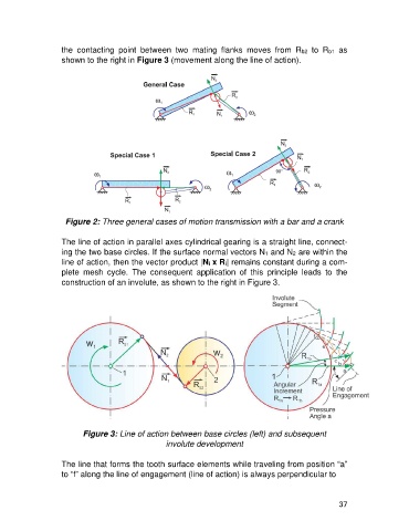
the  contacting  point  between  two  mating  flanks  moves  from  Rb2  to  Rb1  as
                   shown to the right in Figure 3 (movement along the line of action).


                     Figure 2: Three general cases of motion transmission with a bar and a crank

                   The line of action in parallel axes cylindrical gearing is a straight line, connect-
                   ing the two base circles. If the surface normal vectors N1 and N2 are within the
                   line of action, then the vector product |Ni x Ri| remains constant during a com-
                   plete  mesh  cycle.  The  consequent  application  of  this  principle  leads  to  the
                   construction of an involute, as shown to the right in Figure 3.


                          Figure 3: Line of action between base circles (left) and subsequent
                                                   involute development

                   The line that forms the tooth surface elements while traveling from position “a”
                   to “f” along the line of engagement (line of action) is always perpendicular to


                                                                                                      37