
Page 54 - Gear Technology Solutions
P. 54
4.4 Perfect Conjugacy in Straight Bevel Gearsets
Bevel gears with intersecting axes are the topic of a series of three papers
published between October 2014 and January 2015 [2]. A straight bevel
gearset with skew teeth was modeled and a sample was manufactured. This
publication addressed two points, the design of a gearset with low tooth count
and the solution for perfect conjugacy which was successfully achieved. Also,
®
Coniflex straight bevel gears used since the 1940s can achieve perfect con-
jugacy when the machine root angle is equal to the pitch angle of the manufac-
tured gear (generating on the pitch line). This principle applies to any tooth
count combination.
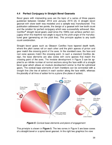
Straight bevel gears such as Gleason Coniflex have tapered depth teeth,
where the pitch cones roll on each other and the pitch apexes of pinion and
gear match the crossing point of the axes. In the standard case, the face and
root cone apexes match the crossing point. In such a standard Coniflex de-
sign, the base elements are also cones with cone apexes that match the
crossing point of the axes. The involute development in Figure 3 can be ap-
plied to an infinite number of normal sections along the face width of a straight
bevel gear which allows an involute development similar to that for cylindrical
gears. The conical base elements of both members can be connected with a
straight line (the line of action) in each section along the face width, whereas
the plurality of all lines of action forms a plane (the plane of action).
Figure 5: Conical base elements and plane of engagement
This principle is shown in Figure 5. The two cones in Figure 5 are base cones
of a straight bevel or a spiral bevel gearset. In the right two graphics the view
39