
Page 58 - Gear Technology Solutions
P. 58
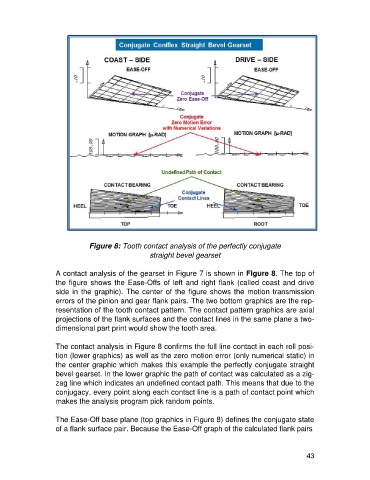
Figure 8: Tooth contact analysis of the perfectly conjugate
                                                   straight bevel gearset

                   A contact analysis of the gearset in Figure 7 is shown in Figure 8. The top of
                   the figure shows the Ease-Offs of left and right flank (called coast and drive
                   side in the graphic). The center of the figure shows the motion transmission
                   errors of the pinion and gear flank pairs. The two bottom graphics are the rep-
                   resentation of the tooth contact pattern. The contact pattern graphics are axial
                   projections of the flank surfaces and the contact lines in the same plane a two-
                   dimensional part print would show the tooth area.

                   The contact analysis in Figure 8 confirms the full line contact in each roll posi-
                   tion (lower graphics) as well as the zero motion error (only numerical static) in
                   the center graphic which makes this example the perfectly conjugate straight
                   bevel gearset. In the lower graphic the path of contact was calculated as a zig-
                   zag line which indicates an undefined contact path. This means that due to the
                   conjugacy, every point along each contact line is a path of contact point which
                   makes the analysis program pick random points.

                   The Ease-Off base plane (top graphics in Figure 8) defines the conjugate state
                   of a flank surface pair. Because the Ease-Off graph of the calculated flank pairs


                                                                                                      43