
Page 471 - Gear Technology Solutions
P. 471
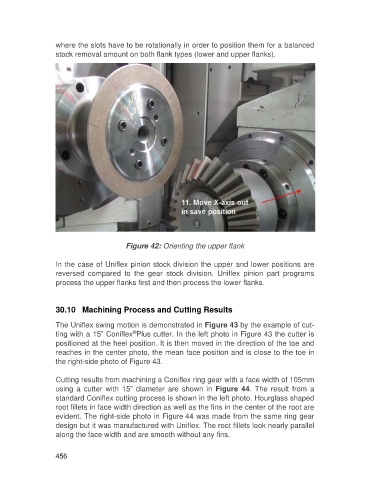
where the slots have to be rotationally in order to position them for a balanced
                   stock removal amount on both flank types (lower and upper flanks).


                                           Figure 42: Orienting the upper flank

                   In the case of Uniflex pinion stock division the upper and lower positions are
                   reversed  compared  to  the  gear  stock  division.  Uniflex  pinion  part  programs
                   process the upper flanks first and then process the lower flanks.


                   30.10   Machining Process and Cutting Results

                   The Uniflex swing motion is demonstrated in Figure 43 by the example of cut-
                                             ®
                   ting with a 15” Coniflex Plus cutter. In the left photo in Figure 43 the cutter is
                   positioned at the heel position. It is then moved in the direction of the toe and
                   reaches in the center photo, the mean face position and is close to the toe in
                   the right-side photo of Figure 43.

                   Cutting results from machining a Coniflex ring gear with a face width of 105mm
                   using  a  cutter  with  15”  diameter  are  shown  in  Figure  44.  The  result  from  a
                   standard Coniflex cutting process is shown in the left photo. Hourglass shaped
                   root fillets in face width direction as well as the fins in the center of the root are
                   evident. The right-side photo in Figure 44 was made from the same ring gear
                   design but it was manufactured with Uniflex. The root fillets look nearly parallel
                   along the face width and are smooth without any fins.


                   456