
Page 382 - Gear Technology Solutions
P. 382
®
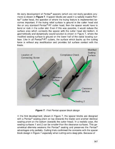
An early development of Pentac spacers (which are not really parallels any-
more) is shown in Figure 7. If spacer blocks are used in a radially truable Pen-
®
tac cutter head, the question of where the truing feature is implemented be-
comes important. If the truing relief surface is ground in the cutter head slot
®
like on any standard Pentac -RT cutter head, then the spacer would have to
bend or rock in the cutter slot. Even if this was possible, it would reduce the
surface area which connects the spacer with the cutter head slot bottom. A
geometrically and dynamically sound solution is shown in Figure 7, where the
modified seating surface is ground on the lower half of the radial locating sur-
®
face. Like in all Pentac -RT cutters, the surface which backs up the cutting
force is without any modification and provides full surface contact with the
blade.
Figure 7: First Pentac spacer block design
In the first development, shown in Figure 7, the spacer blocks are designed
®
with a Pentac seating prism on top (towards the blade) and another identical
seating prism on the bottom (towards the cutter head). In a realistic case, the
seating surfaces 1 and 2 can be smaller than the clearance surfaces. This ge-
®
®
ometrical dilemma weakens the Pentac seating and preserves the Pentac
advantages only partially. Cutting trials confirmed the concerns with the spacer
block design in Figure 7 especially when cutting extra deep jobs. Because of
367