
Page 377 - Gear Technology Solutions
P. 377
oped to provide bevel gear manufacturers with the possibility to implement
changes in the cutting-edge geometry fast by just re-grinding the blade profile
section.
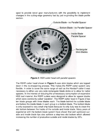
Figure 2: RSR cutter head with parallel spacers
The RSR cutter head shown in Figure 2 uses stick blades which are topped
®
down in the re-sharpening process. This makes the RSR cutter system very
®
flexible. In order to cover the same range of radii as the Hardac cutter it was
®
necessary to either use very wide rectangular blade sticks or to allow for radial
spacers. In the interest of reducing the unnecessary consumption of expensive
HSS tool material, the RSR cutters were designed to allow for spacer blocks
®
which were commonly called “parallels”. The RSR cutter head in Figure 2 has
®
ten blade groups with three blades each. The blade behind the outside blade
and before the inside blade in each group is a bottom blade. The bottom blade
is only exposed to very small chip loads because its only duty was to clean the
slot bottom between the tracks of the outside and inside blade. Many years of
experience with the bottom blade system have shown that well optimized out-
side and inside blade tips also achieve a step-less slot bottom which allowed
increasing the number of productive outside and inside blades by 33%.
362