
Page 372 - Gear Technology Solutions
P. 372
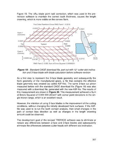
Figure 19. The DRW blade point radii correction, which was used in the pre-
                   revision  software  to  maintain  the  correct  tooth  thickness,  causes  the  length
                   crowning, which is more visible on the convex flank.


                    Figure 19:  Standard CAGE download file, part cut with 12° cutter slot inclina-
                         tion and 3-face blade with blade calculation before software revision

                   As a first step to represent the 3-face blade geometry and subsequently the
                   flank  geometry  of  the  manufactured  gears,  a  file  that  contains  the  effective
                   blade geometry was created (so called A3F-file). The same 3-face cut pinion
                   measured before with the standard CAGE download file (Figure 19) was also
                   measured with a download file, generated with the new A3F-file. The results of
                   this measurement are shown in Figure 20. This measurement achieved a Sum
                   of Errors Squared of 0.000 000 20inch² with corner point deviations in the sin-
                   gle micron range, which is an excellent result.

                   However, the intention of using 3-face blades is the improvement of the cutting
                   conditions, without changing the initially developed flank surfaces. If the A3F-
                   file was used to re-run the tooth contact analysis, then small changes in the
                   path  of  contact  bias  direction  as  well  as  changes  in  the  length  crowning
                   amount could be observed.

                   The development goal of the revised TREFACE software was to eliminate or
                   reduce  any  differences  between  2-face  and  3-face  blades  and  subsequently
                   eliminate the differences between cutter heads with different slot inclination.


                                                                                                     357