
Page 28 - Gear Technology Solutions
P. 28
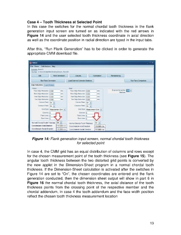
Case 4 – Tooth Thickness at Selected Point
                   In  this  case  the  switches  for  the  normal  chordal  tooth  thickness  in  the  flank
                   generation  input  screen  are  turned  on  as  indicated  with  the  red  arrows  in
                   Figure 14 and the user selected tooth thickness coordinate in axial direction
                   as well as the coordinate position in radial direction are typed in the input tabs.

                   After this, “Run Flank Generation” has to be clicked in order to generate the
                   appropriate CMM download file.


                       Figure 14: Flank generation input screen, normal chordal tooth thickness
                                                     for selected point

                   In case 4, the CMM grid has an equal distribution of columns and rows except
                   for the chosen measurement point of the tooth thickness (see Figure 15). The
                   angular tooth thickness between the two distorted grid points is converted by
                   the  new  applet  in  the  Dimension-Sheet  program  in  a  normal  chordal  tooth
                   thickness. If the Dimension-Sheet calculation is activated after the switches in
                   Figure 14 are set to “On”, the chosen coordinates are entered and the flank
                   generation conducted, then the dimension sheet output will show in part 6 in
                   Figure 16 the normal chordal tooth thickness, the axial distance of the tooth
                   thickness  points  from  the  crossing  point  of  the  respective  member  and  the
                   chordal addendum, In case 4 the tooth addendum and the face width position
                   reflect the chosen tooth thickness measurement location


                                                                                                      13